Respuestas y preguntas sobre la evaluación de habilidades de LinkedIn — SOLIDWORKS
“SOLIDWORKS has become a leading software for 3D modelling and design, ofreciendo ingenieros, diseñadores, y fabricantes una herramienta poderosa y eficiente para hacer realidad sus ideas. En esta guía completa, Estamos encantados de presentar una serie de preguntas de evaluación de habilidades y respuestas diseñado específicamente para SOLIDWORKS usuarios.
Si es un profesional experimentado que busca ampliar sus capacidades o un principiante que desea comprender los conceptos básicos de este poderoso software., Este recurso está diseñado para ayudarle a adquirir competencia en SOLIDWORKS y sus aplicaciones. Únase a nosotros mientras exploramos los conceptos centrales de SOLIDWORKS, including part modelling, assembly design, drawing creation, y más, empowering you to leverage the full potential of this essential tool for your engineering and design needs.”
Q1. Which file contains all the drawing document-specific information, such as specifications for units, drafting standard, font selections, etc.?
- SOLIDWORKS drawing template
- SOLIDWORKS composer file
- SOLIDWORKS part file
- SOLIDWORKS sheet format
Q2. You need to design a steel spring with a pitch diameter of 3 pulgadas, free length of 10 pulgadas, and pitch of 1 pulgada. How would you accomplish this in SOLIDWORKS?
- Create a new sketch of a circle with a diameter of 1 pulgada. Then use the Helix/Spiral curve command and define a height of 10 inches and pitch of 3 pulgadas.
- Create a new sketch of a circle with a diameter of 3 pulgadas. Then use the Helix/Spiral curve command to define a height of 10 inches and pitch of 1 pulgada.
- primero, create a new sketch of a circle of 10 pulgadas. Then use the Helix/Spiral curve command and define by pitch of 1 inch and 3 revolutions.
- Use the Helix/Spiral curve command and define a diameter of 3 pulgadas, height of 10 pulgadas, and pitch of 1 pulgada.
Tercer trimestre. Which single feature could you use to create this image?

- Loft
- Extruded Boss/Base
- Sweep
- Revolved Boss/Base
Cuarto trimestre. Which choice is NOT a fillet type in SOLIDWORKS?
- constant size
- variable size
- rostro
- angled
Q5. Your sketch is not extruding correctly. It does not seem to be a properly closed contour, although from a simple visual inspection, it looks to be fully closed. You think perhaps there are some very small gaps in your contour that are causing the issue. What tool can you use to find these small gaps?
- Quick Snaps
- Rebuild
- Repair Sketch
- Show Error
Q6. Which choice is an example of a skected feature?
- chamfer
- extrusion
- fillet
- shell
Q7. You want to make two circles have the same center point within a SOLIDWORKS sketch. How can you do this?
- Add a tangent relation between the circles
- Add a concentric relation between the circles
- Add a horizontal relation between the circles
- Add an equal relation between the circles
Q8. Which reference geometry is NOT available in SOLIDWORKS?
- sphere
- plane
- punto
- axis
Q9. Specifying two lines to be perpendicular to each other would be an example of what?
- En este curso siempre aprenderás POR QUÉ
- relation
- extrude
- dimension
Q10. You want to focus on a single component within your assembly and hide all the rest. How can you do this?
- Right-click the component you want to focus on and select Change Transparency
- Right-click the component you want to focus on and select Hide
- Right-click the component you want to focus on and select Isolate
- Right-click the component you want to focus on and select Suppress
tecnicos. What will Save As do on an existing saved part?
- It will delete the original part and save the current part with a new name
- It will keep the original part and save the current path with a new name
- It will save both the original part and the new part in the current state
- It will rename the original part
Q12. You want to show a list of the raw materials, subassemblies, intermediate assemblies, subcomponents, and parts, and the quantities of each, needed to manufacture an end product. What would be useful to accomplish this?
- bill of material
- isometric view
- exploded view
- hole list
P13. Freezing a portion of a model can be used if you work with complex models with many features. Por qué
- Freezing the features helps to show only the critical features of the model
- Freezing the features helps to show the internal features of the model
- Freezing the features helps to reduce the rebuild time and prevent unintentional changes to the model
- Freezing the features helps to show the external features of the model
Q14. Which single features could you use to design a cube, a sphere, and a paperclip, respectivamente?
- Revolved Boss/Base, Shell, and Sweep
- Shell, Revolved Boss/Base, and Extruded Boss/Base
- Extruded Boss/Base, Revolved Boss/Base, and Sweep
- Borrador, Extruded Boss/Base, and Shell
P15. Which choice is NOT a standard mate within SOLIDWORKS?
- parallel
- coindicent
- igual
- concentric
Q16. How would you temporarily remove a feature from a model?
- Click the feature in the FeatureManager design tree or graphics area, then select Suppress
- Drag the feature to the Suppression folder, located at the top of the FeatureManager design tree
- You cannot remove features temporarily-you can only delete them completely
- Drag the feature to the bottom of the FeatureManager design tree, then drag the Suppression bar above it
P17. You want to show an assembly’s components spread out and positioned to show how they fit together when assembled. Cómo se logra esto?
- Use Assembly Visualization
- Use a bill of materials
- Use isometric view
- Use exploded view
P18. How would you fix a Lofted Boss/Base feature that appears twisted?
- Drag the loft connectors to the correct position, or use guide curves
- Reduce the spacing between the loft profiles, then scale the loft body as required
- Loft shapes are driven entirely by the loft profiles, adjust the skecthes to remove any ambiguity in the loft path
- Ensure that the Twist Along Path option is not selected
Q19. When creating a sweep feature, you receive this error: “Cannot get to a point on the path to start with. For an open path, the path must intersect with the section plane.” How can you fix this?
- Ensure that the path sketch touches the profile sketch at some point
- Select the Path Merge option within the sweep feature
- Select the Path Intersection option within the sweep feature
- Edit the path sketch and reduce any areas of tight curvature
P20. With injection molding, one common manufacturing requirement or preference is applying a taper or angle to faces to help with part removal from the mold. Which feature can help you meet this requirement?
- Loft
- Borrador
- Wrap
- Sweep
P21. You want to simplify a very large and complex assembly to improve performance while working within it. What should you use?
- DFMXpress
- SpeedPak
- a flexible subassembly
- Design Checker
[referencia](https://help.solidworks.com/2014/english/SolidWorks/sldworks/c_Improving_Large_Assembly_Performance_SWassy.htm
P22. If you are working with ISO standards, which projection method would you most likely be using?
- second angle projection
- fourth angle projection
- first angle projection
- third angle projection
Q23. You have a single line within a sketch that you would like to split into three separate lines. How can you achieve this?
- Use the Offset Entities tool
- Use the Split Line tool
- Use the Split Entities tool
- Use the Split tool
P24. What controls the direction and magnitude of a spline curvature?
- inflection point
- control point
- spline point
- spline handle
P25. You want to build a new part within an assembly to ensure in-context relations and dimensions. You also want to save out this part file as its own unique file. After navigating to the Assembly ribbon tab, what do you do next?
- Under Insert Component, select Part to create a new in-context part. Right-click the new part and select isolate
- Select Insert Component to create a new in-context part. Right-click te new part and select Save Part (in External File)
- Under Insert Components, select New Part to create a new in-context part. Right-click the new part and select Save Selection
- Under Insert Components, select New Part to create a new in-context part. Right-click the new part and select Save Part (in External File)
Q26. The ribbon bar at the top of your SOLIDWORKS screen has disappeared. How can you get it back?
- Click View > Toolbars > CommandManager
- Click View > Toolbars > FeatureManager
- Click View > Toolbars > MotionManager
- Click View > Toolbars > Task Pane
Q27. Representing a three-dimensional object by a number of two-dimensional views is generally called
- isometric projection
- oblique projection
- object projection
- orthographic projection
P28. How can you rename a feature?
- Select the feature name and press F2, or slow-double-click the feature name
- Select the feature name and press F3 key, or right-click the feature name
- Select the feature name and press F7, or quick-double-click the feature name
- Select the feature name and press F5 key, or double-click the feature name
Q29. When using the Fillet tool, what does the Tanget Propagation option do?
- It creates a fillet that is tanget to the direction of view
- It creates a fillet that varies in size, depending on lcoal tangency
- It creates a constant-size fillet around all selections
- It extends the fillet to all faces that are tangent to the selected face
Q30. You notice that one of the subassemblies in your main assembly is rigid and does not have mobility it should. How can you resolve this issue?
- Select the subassembly and then select Make Subassembly Flexible from the context menu
- Select the subassembly and then select Set Resolved from LightWeight from the context menu
- Select the subassembly and then select Edit Assembly from the context menu
- Select the subassembly and then select Make Independent from the context menu
P31. You dimension an arc in a drawing and notice that the dimension is coming in as the radius value. You want to show the diameter value. Para hacer esto, first you click the dimension to open the dimension PropertyManager. What do you do next?
- Sobre el Líderes pestaña, Seleccione Diameter
- Sobre el Otro pestaña, Seleccione Diameter
- Sobre el Valor pestaña, y seleccione Diameter
- Sobre el Valor pestaña, seect Override Value
Q32. En la imagen de abajo, which are the parents and children of the Vertical Boss Feature?
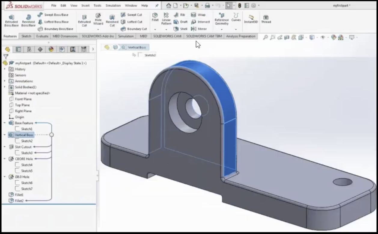
- The parent is Base Feature; the children are Slot Cutout, Sketch3, CBORE Hole, and Fillet2
- The parent is Vertical Boss; the childre are Base Feature, Slot Cutout, Sketch3, CBORE Hole, and Fillet2
- The parent is Base Feature; the children are Vertical Boss, Slot Cutout, Sketch3, CBORE Holde, and Fillet2
- The parents are Vertical Boss and Base Feature; the children are Slot Cutout, Sketch3, CBORE Hole, and Fillet2
para celebrar el éxito y resaltar las áreas de oportunidad. en esta imagen, which parts are fixed?

- BASE
- LINK 3
- LINK 5
- LINK 1
P34. What is this image an example of?

- a hole table
- a revision table
- a tolerance table
- a punch table
entonces solo habrá falla si el defecto ocurre en cada capa y estas están todas alineadas al mismo tiempo. What type of dimensioning is shown here?

- smart dimensioning
- angular running dimensioning
- ordinate dimensioning
- chain dimensioning
Q36. En la imagen de abajo, what types of hole are A1 and B1 respectively?

- countersink and counterbore
- counterbore and countersink
- standard and threaded/tapped
- threaded/tapped and standard
P37. What is this sketch an example of?
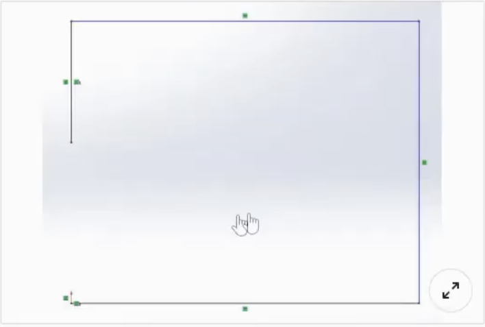
- an open contour sketch
- a multi-contour or intersecting sketch
- a triple contour sketch
- a closed contour sketch
P38. Can this skecth be extruded?
- Sí, you can extrude it using the standard extrude boss option
- Sí, you can extrude it using the Selected Contours option
- No, the sketch is an open contour and this cannot be extruded
- Sí, you can extrude it using the Thin Feature option
P39. Why is it useful to suppress a feature?
- Suppressing changes the color of a feature. This is useful to help easily distinguish between different features.
- Suppressing removes a feature from a model, but does not delete it. This is useful if you need that feature back in the future.
- Suppressing removes a feature from a model forever. This is useful if you no longer need that feature.
- Suppressing makes a feature transparent. This is useful if you ever need to see through a feature when modeling.
Q40. Which choice is not a standard view orientation in SOLIDWORKS?
- atrás
- abajo
- Correcto
- front
P41. What type of view is used to show a portion of some parent view, usually at an enlarged scale?
- detail view
- auxiliary view
- break view
- vista de la sección
P42. How can you create relationships between parts within an assembly?
- Use mates.
- Use constraints.
- Use relations.
- Use dimensions.
Q43. What is required to create a solid using the Swept Boss/Base tool?
- a profile and a path
- a sketch and an axis of revolution
- atleast two profiles
- a sketch
Q44. Which statement best describes the term “parametric modeling”?
- This type of modeling is often compared to working with modeling clay.
- The dimensions and relations used to create a feature are captured and stored in the model.
- You can simply push and pull the geometry until you arrive at the shape you require.
- Dimensions and relations are not captured or stored within the model.
P45. What is required to create a solid using the Extruded Boss/Base tool?
- at least two profiles
- a sketch and an axis of revolution
- a sketch
- a profile and a path
Q46. Which choice is an example of an applied feature?
- extrusion
- revolve
- fillet
- sweep
P47. How can you change the size of a toolbox screw in an assembly?
- Right-click the component and select Edit Toolbox Component.
- Toolbox part sizes cannot be changed once added. You have to delete the screw and then readd one of the correct size.
- Edit the screw part and add a scale feature using only the required axes.
- Open the screw part, then manually adjust the dimensions and save as a copy.
Q48. Which choice is not a standard 3D view in SOLIDWORKS?
- dimetric
- trimetric
- isometric
- oblique
Q49. You are designing a robotic arm assembly. You want the first link of the arm to be able to rotate about the base, but only a total of 270 degrees from the start point and no further. How would you achieve this?
- Use an Angle mate.
- Use a Mechanical mate.
- Use a Limit Angle mate
- Use a Gear mate.
Q50. How can you reattach a broken reference in a derived split part?
- Right-click the filename at the top of the FeatureManager design tree and select Relink Stock Part.
- Once derived part references are broken, they cannot be readded. Consider resplitting the part.
- Locate the child part using SOLIDWORKS Explorer and select Relink Parent.
- Edit the stock feature at the start of the FeatureManager design tree, then adjust the Defining Stock Part option.
P51. You have designed a plastic part that you want to split and save in two separate unique parts. You use the Split tool to split the part in half and create the two bodies. What do you do next?
- Navigate to the Solid Bodies folder, right-click the body name, and select Isolate to save to a new file. Repeat for the other body.
- Within the Split tool, select Consume Bodies.
- Within the Split tool, select Save as New Files.
- Within the Split tool, click File, double-click the body name, type a name for the new part, and click Save.
Q52. What is required to create a new 2D sketch?
- any existing geometry
- any existing plane or curved face
- any existing plane or planar face
- any planar or curved surface
Q53. You want to enlarge your current design by 3%. What tool would you use?
- Extrude
- Loft
- Scale
- Truncate
Q54. Earlier within your part design, you created a sketch. Now you want to make a copy of this sketch to use on a different plane or face. You want to ensure that the two sketches will always be the same, so that if you modify the original sketch, the new sketch is updated to reflect the same changes. How can you achieve this?
- Copy and paste the original sketch.
- Copy and paste the original sketch using Paste Special.
- Create a composite sketch.
- Create a derived sketch.
Q55. When creating sketches, small boxes show up next to the sketch lines. What are these boxes called?
- check boxes
- locks
- statuses
- relaciones
P56. You notice your sketch is blue. How can you make your sketch fully defined?
- Add in any additional required features.
- Add in the additional dimensions or relations.
- Nada, the sketch is already fully defined.
- Remove any additional dimensions or relations.
P57. Which sketch relation can you NOT apply to a rectangle?
- coincident
- collinear
- concentric
- fix
P58. Using Autodimension in drawing mode can create dimensions in which styles?
- baseline and ordinate
- chain and baseline
- ordinate and chain
- chain and linear
Q59. What type of sketch do you need to create a sheet metal part?
- a closed sketch
- an open sketch
- an open and closed sketch
- You don’t need a sketch to create sheet metal parts.
Q60. How can you easily visualize parent/child arrows on the FeatureManager design tree?
- In the FeatureManager design tree, right-click the top level of the part/assembly and select SOLIDWORKS PDM.
- In the FeatureManager design tree, right-click the top level of the part/assembly and select Hide/Show Tree Items.
- In the FeatureManager design tree, right-click the top level of the part/assembly and select Show Flat Tree View.
- In the FeatureManager design tree, right-click the top level of the part/assembly and select Dynamic Reference Visualization.
Q61. You created a counterbore hole using the Hole Wizard. How can you automatically dimension all aspects of the counterbored hole in a drawing?
- Use the Smart Dimension annotation tool.
- Use the Datum Feature annotation tool.
- Use the Hole Callout annotation tool.
- Use the Ordinate Dimension annotation tool.
P62. How can you add an angle to all extruded faces of a feature?
- Set a Draft in the extrude feature.
- Activate the Thin Feature option in the extrude feature.
- Set the end condition to Offset From Surface in the extrude feature.
- Set the start condition to Offset in the extrude feature.
Q63. What is the file extension for a SOLIDWORKS drawing template?
- .dwg
- .slddrw
- .slddrt
- .drwdot
Q64. Are planes required to start a 2D sketch?
- No, 2D sketches can be created on any planar face of a feature.
- Sí, all sketches must begin on a plane, but the feature start point can be offset.
- No, 2D sketches can be started at any point using the Create Floating Sketch option.
- No, 2D sketches can be created on any flat or curved surface.
Q65. How can you cut one body from another body within a multi-body part?
- Use the Body Remove feature.
- Use the Combine feature with the Subtract operation.
- Use the Cavity feature.
- Use the Merge Result > Remove Body option.
Q66. You want to share a SOLIDWORKS assembly with another SOLIDWORKS user so that user can edit it. What is the best way to do this?
- Save the assembly as a sldasm file and send the file to the user.
- Save the assembly as a single part (.sldprt file) to include all assembly contents.
- Use Pack and Go to package and send all assembly files.
- Save the assembly as a 3D PDF and select the Enable Editing option.
Q67. Which choice is not a category of mates in SOLIDWORKS?
- Estándar
- Avanzado
- Básico
- Mecánico
P68. You want to share a SOLIDWORKS assembly with another SOLIDWORKS user so that user can edit it. What is the best way to do this?
- Save the assembly as a sldasm file and send the file to the user.
- Save the assembly as a single part (.sldprt file) to include all assembly contents.
- Use Pack and Go to package and send all assembly files.
- Save the assembly as a 3D PDF and select the Enable Editing option.
P69. How can you create a drawing view in SOLIDWORKS?
- Right-click on the part and choose “Create Drawing View.”
- Ve a la “Insertar” menu and select “Drawing View.”
- Utilizar el “Vista” toolbar and click on “New Drawing View.”
- Access it through the “Herramientas” menu under “Drawing Views.”
Q70. When working with assemblies in SOLIDWORKS, what does the “Collision Detection” tool help you identify?
- Interference or clearance issues between components.
- The weight of individual assembly parts.
- The center of mass for the entire assembly.
- The assembly’s total volume.
Deja una respuesta
Debes iniciar sesión o registro para agregar un nuevo comentario .